Many people when first contacting ultra‑high‑pressure waterjet will form a natural judgement: if the guide rail, lead screw and servo system of waterjet machine tool can achieve high positioning accuracy, then the parts it cuts should also be equally precise. However, real Abrasive Waterjet (AWJ) machining is not that simple.
There is one critical difference between waterjet and traditional milling cutters or drill bits: milling cutter is a “hard cutting tool”, while waterjet is a “fluid cutting tool”. The nozzle position can be extremely accurate, but after high‑speed jet enters the material, it will be affected by many factors such as feed rate, abrasive mass flow rate, water pressure, material thickness and cutting path.
Therefore: the nozzle moves accurately does not equal the waterjet cuts accurately; machine positioning accuracy does not equal the final part must be accurate. This is where the real interest of precision waterjet technology lies.
1 How an Ultra‑high‑pressure Waterjet Works
An ultra‑high‑pressure abrasive waterjet equipment is not simply “using a high‑pressure pump to shoot out water”. From ordinary tap water to high‑speed abrasive jet that can cut metal, stone, glass and composite materials, multiple systems need to work together.
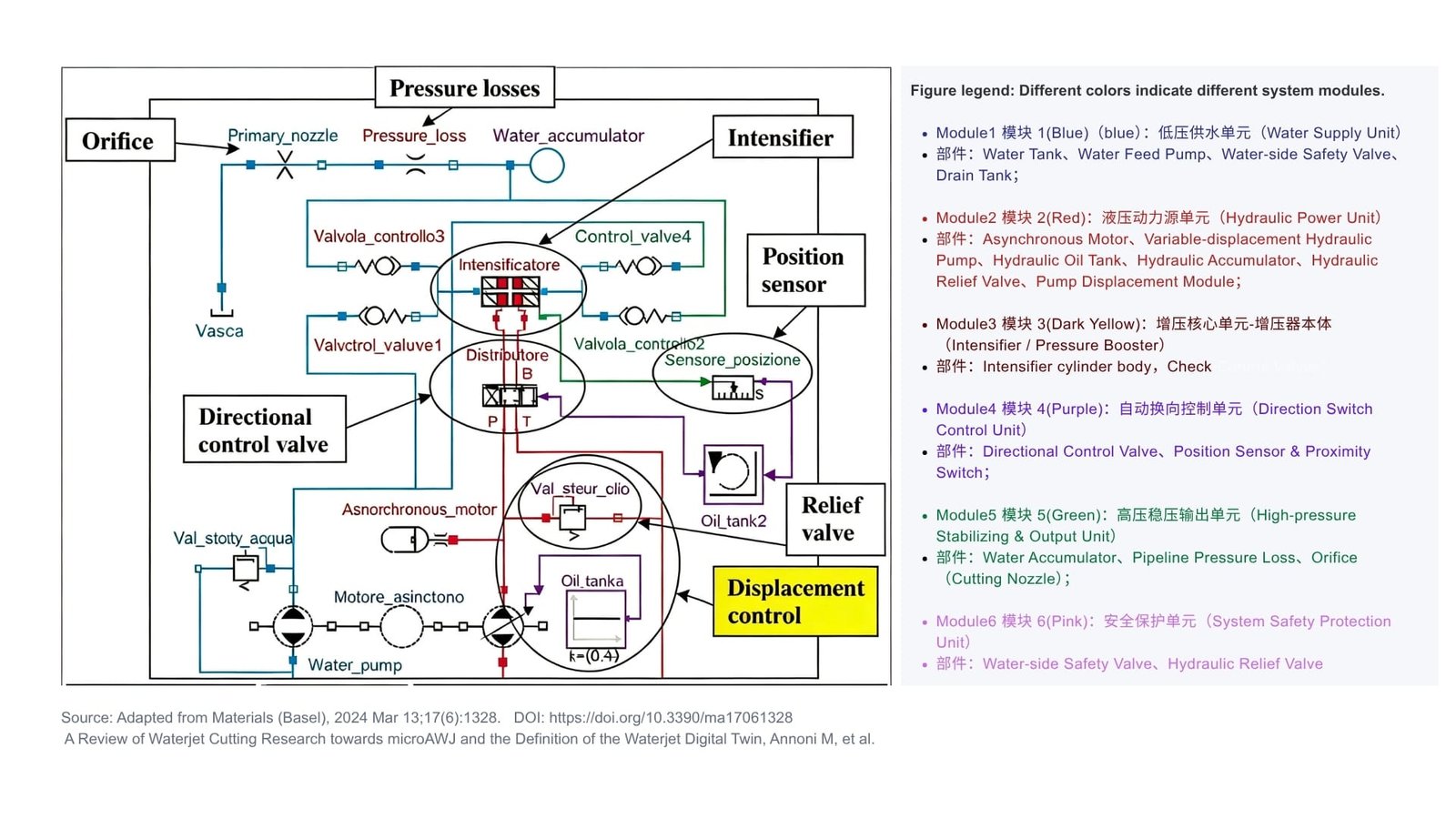
For easier understanding, we can divide the core pressurizing system of waterjet into six physical hardware modules:
- 1. Water Supply Unit
- 2. Hydraulic Power Unit
- 3. Intensifier / Pressure Booster Unit
- 4. Direction Switch Control Unit
- 5. High‑pressure Stabilizing & Output Unit
- 6. System Safety Protection Unit
These six modules complete one thing together: convert ordinary water into stable, safe, high‑cutting‑power ultra‑high‑pressure abrasive waterjet. Let us look at what they do one by one.
2 Module 1: Water Supply Unit — Send Water Stably
Main Components:
- – Water Tank
- – Water Feed Pump
- – Water‑side Safety Valve
- – Drain Tank
What it does:
The water supply unit provides continuous and stable water source for the whole pressurizing system. Water tank stores process water; water feed pump delivers water to intensifier; water‑side safety valve provides basic over‑pressure protection; drain tank collects drained or circulated water.
It solves this most basic problem: “Can we get stable water supply all the time?” If water supply is insufficient, intensifier cannot work normally; if water supply is unstable, subsequent high‑pressure system will also be influenced.
What it cannot solve:
It does not generate ultra‑high pressure itself, and cannot directly decide whether the workpiece is cut accurately in the end.
Analogy:
It is just like the water‑supply system of water dispenser. It sends water stably, but cannot decide whether this water can cut steel plate.
3 Module 2: Hydraulic Power Unit — Provide Power for Intensifier
Main Components:
- – Asynchronous Motor
- – Variable‑displacement Hydraulic Pump
- – Hydraulic Oil Tank
- – Hydraulic Accumulator
- – Hydraulic Relief Valve
- – Pump Displacement Module
What it does:
Hydraulic power unit is the “power heart” of the whole pressurizing system. Asynchronous motor outputs mechanical energy; variable‑displacement hydraulic pump converts mechanical energy into hydraulic oil pressure and flow, then drives intensifier piston to move back and forth. The pump displacement module adjusts variable pump displacement so hydraulic system can change output according to working condition. Hydraulic accumulator improves dynamic response and reduces pressure fluctuation of hydraulic system, and hydraulic relief valve offers over‑pressure protection for hydraulic side.
This module mainly decides: power capacity, pressure capacity, flow capacity, dynamic response, hydraulic system stability.
What it cannot solve:
It only “outputs power”, but cannot judge by itself: how fast should we cut now? It also cannot judge: when entering corner area, should abrasive flow increase or decrease?
Analogy:
It likes a car engine. Even with large horsepower, it cannot guarantee the car runs along road precisely.
4 Module 3: Intensifier / Pressure Booster Unit — Turn Ordinary Water into Ultra‑high‑pressure Water
Main Components:
- – Intensifier Cylinder Body
- – Check‑Control Valves
What it does:
This is the core of waterjet pressurizing system. The intensifier uses piston area difference between hydraulic side and high‑pressure water side, and turns hydraulic power into much higher water pressure. After pressurization, ordinary water gets enough pressure, and prepares for forming high‑speed waterjet. So we can treat it as the “pressure‑generating core” of waterjet.
What it cannot solve:
The intensifier builds up pressure, but it does not know the drawing of workpiece. It cannot judge actively: when to slow down, how to run round corner, how much abrasive to feed, whether the kerf is vertical.
Analogy:
It is like a super‑power hand air pump. It only pumps pressure up, but will not decide how to use this pressure.
5 Module 4: Direction Switch Control Unit — Make Intensifier Keep Working
Main Components:
- – Directional Control Valve
- – Position Sensor
- – Proximity Switch
What it does:
Intensifier piston cannot keep moving toward one single direction. When piston reaches stroke end point, hydraulic oil flow direction needs to change timely to make piston move backward. Position sensor and proximity switch detect piston position, and directional control valve switches hydraulic oil flow direction according to control logic. Then: piston reciprocating movement → automatic direction switch → continuous pressurization → continuous high‑pressure water output.
What it cannot solve:
Its main task is to guarantee intensifier works continuously and reliably, not directly control workpiece dimension. One point worth noticing: direction‑switch process may bring pressure and flow fluctuation. If these fluctuations pass to high‑pressure water side, jet stability and machining quality will be affected. So it is not a precision‑control module, but cannot be totally separated from machining quality.
Analogy:
It is like an auto push‑pull hand. It keeps pushing and pulling to make air pump work continuously.
6 Module 5: High‑pressure Stabilizing & Output Unit — Prevent Jet From Blowing Strong‑weak Alternately
Main Components:
- – Water Accumulator
- – Pipeline Pressure Loss
- – Orifice / Cutting Nozzle
What it does:
Because intensifier works in reciprocating mode, generated high‑pressure water has certain pressure pulsation. Water accumulator buffers pressure fluctuation on high‑pressure side and makes output more stable. At the same time, real system has high‑pressure pipeline pressure loss. Finally high‑pressure water arrives at orifice (cutting nozzle), and forms high‑speed jet through tiny hole. For abrasive waterjet, abrasive mixes with high‑speed waterjet and becomes Abrasive Waterjet for material cutting.
What it cannot solve:
This module can get more stable jet output, but cannot judge actively: “Now it is straight‑line cutting, we should cut fast.” Or “Now we enter corner, need change machining strategy.”
It solves the problem: “Can jet come out stably.” Not: “How should jet cut workpiece.”
Analogy:
It is a combination of reservoir and nozzle. It stabilizes water flow and turns water into high‑speed jet, but will not decide what shape we need to cut.
7 Module 6: System Safety Protection Unit — Make Sure High‑pressure Equipment “Do Not Break Down”
Main Components:
- – Water‑side Safety Valve
- – Hydraulic Relief Valve
What it does:
Waterjet runs under extremely high pressure, so system needs reliable over‑pressure protection. Water‑side safety valve protects high‑pressure water circuit. Hydraulic relief valve protects hydraulic oil circuit. When system pressure rises abnormally, valves release pressure to keep pressure within safe range, and protect pumps, valves, pipelines and other key parts.
What it cannot solve:
It is responsible for safety, not machining accuracy.
Analogy:
It works like the safety valve of pressure cooker. It prevents pressure cooker from exploding under over‑pressure. Whether food cooks well depends on heating power and time.
8 What Do Six Hardware Modules Decide?
We can easily understand when putting six modules together:
| Module | Core Function | Main Problem Solved |
| Water Supply Unit | Stable water supply | Availability of stable feed‑water |
| Hydraulic Power Unit | Supply hydraulic power | Availability of sufficient drive power |
| Intensifier Unit | Water‑pressure amplification | Generation of ultra‑high pressure |
| Direction Switch Control Unit | Piston reciprocation | Continuous pressurisation capability |
| High‑pressure Stabilizing & Output Unit | Buffer, convey and jet water | Stable jet delivery |
| System Safety Protection Unit | Over‑pressure protection | Safe equipment operation |
One sentence summary for six modules: they decide whether waterjet “can work, have enough power, keep stable and run safely”. One important point: hardware is necessary foundation for precision machining, but cannot guarantee final machining quality alone. Real material‑cutting process is more complex.
9 Layer‑1 Control: Motion Control — Make Nozzle “Move Accurately”
Six hardware modules solve: “Can jet be generated?” While CNC motion control solves another question: “Where should nozzle go?”
Motion control system mainly controls:
- – X/Y/Z coordinate
- – Feed rate
- – Acceleration and deceleration
- – Corner movement
- – CAM tool path
- – Nozzle motion trajectory
For example, drawing requires cutting a circle. CNC calculates circular path and controls nozzle to move along this path. If guide rail, lead screw and servo have high precision, nozzle can finish circular path very accurately. But: the trajectory nozzle follows is not equal to real cutting trajectory of jet inside material. This is one of key points for precision waterjet machining.
10 Why “Nozzle Runs Accurately But Kerf Is Not Accurate”?
Because waterjet is not solid cutting tool. After high‑speed abrasive waterjet enters material, it will be influenced by many factors: feed rate, water pressure, abrasive mass flow rate, material type, material thickness, nozzle parameter, cutting path, corner acceleration‑deceleration.
This may cause such phenomenon: nozzle moves along correct path, but jet deflects, lags or spreads inside material. Finally these defects occur: Kerf Width change, Kerf Taper, Jet Lag, Surface Roughness change, Waviness, Dimensional Error.
So: nozzle positioning accuracy ≠ final part machining accuracy.
11 Layer‑2 Control: AWJ Process Control — Make Jet “Cut Correctly”
Then we need Layer‑2: AWJ Process Control. This layer no longer only cares nozzle position, but thinks: under current motion status, what status should jet keep to cut material?
Key process variables include: feed rate, abrasive mass flow rate, water pressure, water flow rate, material type, material thickness.
These parameters influence each other. For example: straight‑line high‑speed cutting and corner low‑speed cutting use same nozzle and same pressure, but real machining status is totally different.
12 Why Corners Easily Bring Machining Problems?
Assume waterjet cuts straight line at high speed, and meets a 90‑degree corner. For machine to finish corner movement, CNC usually needs to reduce feed rate. If system only does one thing: “slow down speed, leave other parameters unchanged”. The interaction status between jet and material will change.
This may cause: kerf width change, kerf taper change, bad surface quality on corner zone, local dimensional error. So one important idea for precision AWJ: when motion status changes, process parameters should also change cooperatively.
13 Let Speed, Abrasive Flow and Tool Path Work Together
For example, when feed rate changes, system can coordinate and adjust abrasive mass flow rate according to machining model, together with path compensation, to reduce bad influence from motion change on kerf geometry quality. Simple understanding: when machine slows down, we cannot only “make machine run slow”, but also consider whether jet cutting status changes.
This is motion‑process cooperative control. It is a valuable technical direction for 3‑axis AWJ. Especially for 3‑axis machine without tilting head which cannot compensate kerf taper mechanically, cooperative optimization of process parameter and tool path can improve precision machining capacity.
14 Layer‑3 Control: Quality Prediction and Optimization — Check What the Final Part Looks Like
At Layer‑3, we no longer care: where is nozzle? Or only: what is water pressure? We care: what does final machined part look like?
Quality indexes include: kerf width, kerf taper, surface roughness, surface waviness, dimensional accuracy, corner error.
At this time we need mathematical models. For example, use kerf taper model to research: how kerf taper changes when pressure, abrasive mass flow rate, feed rate, material and thickness change. Use roughness model to study: how to select process parameters to meet geometry requirement and get target surface quality.
Finally we can convert the target “What kind of part we want” into “What motion and process parameters machine should use”. This is real machining optimization.
15 Real Three‑layer Control Logic for Precision Waterjet
Put whole system together and the logic becomes clear:
– Layer‑1: Motion Control
Solve: Where should nozzle go?
Control: XYZ, feed rate, acceleration‑deceleration, corner, tool path.
– Layer‑2: AWJ Process Control
Solve: How should jet cut?
Coordinate: feed rate, abrasive mass flow rate and necessary jet parameters.
– Layer‑3: Quality Prediction and Optimization
Solve: Whether cutting result meets requirement?
Focus on: taper, kerf width, roughness, waviness, dimensional accuracy.
Then optimize by model: motion parameters + process parameters + path compensation. So form closed‑loop: Motion → Process → Quality → Optimization → Feedback to Motion and Process.
16 What Is the Real Secret of Precision Waterjet?
The answer is simple: do not make one single part extremely precise, but make all systems take responsibility for “final machined part”.
Six hardware modules provide stable physical capacity: Is water enough? Is pressure enough? Is power stable? Is jet stable? Is equipment safe?
- Layer‑1 motion control answers: Where should nozzle go?
- Layer‑2 process control answers: How should jet cut?
- Layer‑3 quality prediction and optimization answers: Whether finished part meets target? How to adjust parameters?
Finally we get complete technical chain:
High‑pressure Hardware → Stable Jet → Precise Motion → Cooperative Process Parameters → Quality Prediction → Path & Process Compensation → Parts closer to target geometry and surface quality
17 What Is the Difference Between Ordinary Waterjet and Precision Waterjet?
One‑sentence explanation: ordinary waterjet mainly controls “where nozzle is”; precision waterjet further controls “how jet cuts inside material”.
Control flow of ordinary system:
Drawing → CAM → CNC → Nozzle Motion → Cutting Finish
More advanced precision AWJ system flow:
Drawing Target → Motion Planning → Process Parameter Optimization → Jet Cutting → Quality Prediction → Path / Process Compensation
Performance differences rarely come from adding large numbers of new mechanical parts. The decisive distinction is whether system design connects equipment capabilities to final‑part quality.
Ultra‑high‑pressure abrasive waterjet is a multidisciplinary machining technology drawing on mechanical engineering, hydraulics, high‑pressure water systems, abrasive‑feed systems, CNC motion control and empirical process models.
Achieving precision waterjet performance is not simply about building stiffer guide‑rails, better lead‑screws or raising operating pressure. While hardware improvements are beneficial, genuine precision depends on integrating hardware, motion behaviour, jet physics, abrasive delivery and part‑quality expectations into one unified system.
The desired operating sequence: real‑time changes in machine motion → co‑ordinated adjustment of process parameters → controlled jet‑cutting behaviour → prediction and optimisation of kerf taper and surface texture → final‑part geometry closer to the design intent.
This is the true secret of precision waterjet machining: the goal is not merely to make the nozzle move more accurately, but to treat nozzle‑motion programming and jet‑material cutting behaviour as one unified problem.
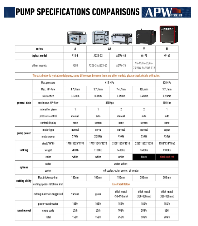
If you are interested in waterjet technology, please feel free to contact our sales team or leave us a message. We also recommend reviewing the technical information for APW high-pressure pumps as a reference for further understanding of waterjet systems.