water jet technology is suit to industriy cutting.
As the drafter of the national standard for waterjets in China(GB/T26136-2018), we hope that our expertise can contribute to your business success.

If the water jet technology explanations below are not clear enough, please feel free to contact us. We are more than willing to answer your questions and address your concerns.
Water Jet Technology and Principles
| Waterjet / Water Jet | A high – speed water stream ejected through a tiny nozzle after being pressurized by a high – pressure pump, used as a cutting tool, commonly known as a waterjet. Compared with other cutting methods, the advantages of abrasive water jet technology include: extremely versatile process; no heat – affected zone; no mechanical stress; easy programming; thin jet diameter (0.1mm); capable of processing extremely fine geometric shapes; suitable for cutting thin materials; can cut materials less than 400mm thick (taking iron as a reference); supports stack cutting; minimal material loss during cutting; simple fixtures; low cutting force (less than 1KG during cutting); a single jet setup can handle almost all abrasive jet processing tasks; easy to switch from single – head to multi – head use; can quickly switch from pure waterjet to abrasive waterjet; reduces secondary processing; almost no burrs. |
| Ultra – High – Pressure Waterjet | According to the Chinese national standard GB26136 – 2018 “Ultra – High – Pressure Waterjet Cutting Machine”, a waterjet with a pressure range of 250 – 400MPa is an ultra – high – pressure waterjet, which has higher cutting ability and precision. |
| Pure Waterjet | A high – pressure waterjet without abrasives, mainly used for cutting soft materials such as foam, rubber, and food.
|
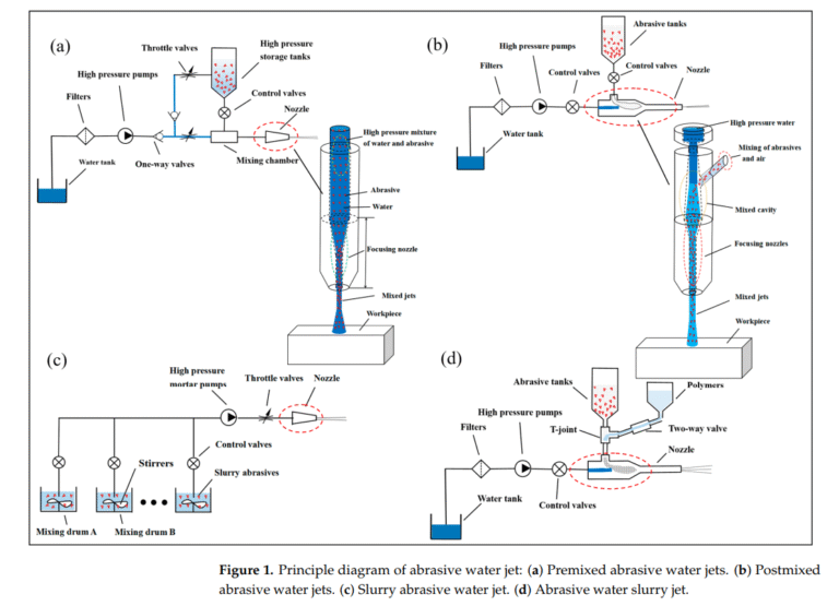
| Abrasive Waterjet | Mix abrasive materials such as garnet and carborundum into the waterjet to enhance the cutting ability for hard materials. Abrasive waterjets are more powerful than pure waterjets and can cut hard materials such as metals, glass, stone, and metal. However, in water jet technology , due to the hardness limit of the abrasives, waterjets generally cut materials with a hardness of 6.5 or less. Fortunately, most processing materials meet this requirement. |
| Cavitation Effect | When the local pressure of the waterjet drops sharply, bubbles are formed. When these bubbles burst, they generate a strong impact force to assist in material cutting. |
Water jet Cutter Components
| High – Pressure Pump | The core component of a waterjet cutting machine and the key of water jet technology . Common types include plunger pumps and intensifiers, which are used to pressurize water to the required pressure. |
| Nozzle | Usually made of gemstones or hard alloys, its aperture size and shape have a significant impact on the speed, shape, and cutting effect of the waterjet. The commonly used aperture is 0.33mm. The nozzle of a waterjet is a consumable item. It usually needs to be replaced after about 100 hours of use. Of course, if the water quality is better or the pressure is lower, its lifespan will be extended; otherwise, it will be shortened. |
| Abrasive Tube | The final component of the abrasive waterjet cutting head. After water passes through the gemstone nozzle, it forms a supersonic jet. Abrasives are sucked into the head through the Venturi effect in the mixing chamber, and then water and abrasives are discharged through the mixing tube. The abrasive tube of a waterjet, like the nozzle, is a consumable item, and its lifespan is usually 50 – 100 hours. |
| Cutting Head | Integrates the nozzle and abrasive delivery system (for abrasive waterjets), and can accurately control the cutting position and trajectory according to the instructions of the numerical control system. There are 3 types of waterjet cutting heads. The 3 – axis cutting head can only move forward, backward, left, right, up, and down. The AB5 – axis cutting head can tilt ±12° to compensate for the taper problem of the waterjet itself. The AC5 – axis cutting head can tilt the A – axis ±89° and rotate the C – axis 360°, enabling 3D cutting of complex curved surfaces. If a rotating axis is added to the platform or a robotic arm is used to drive the cutting head, more cutting possibilities can be achieved, which also means a wider business scope. |
| High – Pressure Pipe | The high – pressure pipeline in the waterjet safely transports the water generated by the high – pressure pump to the cutting head. It includes flexible stainless – steel pipes (with outer diameters of 1/4 inch, 3/8 inch, or 9/16 inch), tees, elbows, and swivel joints. |
| Numerical Control System | Used to control the movement trajectory and cutting parameters of the cutting head, achieving an automated and high – precision cutting process. |
| Check Valve | A one – way switch in the waterjet pump that only allows media such as water to flow in one direction, preventing water from flowing back. |
| Drive Motor | The drive motor in the motion system receives positive and negative currents from the CNC drive amplifier and provides clockwise or counterclockwise rotation to move the machine. It can use direct – drive motors or servo motors. Direct – drive motors have higher power and better stability, while servo motors are more energy – efficient. |
| Intensifier | The heart of the high – pressure pump, a core component for generating high – pressure waterjets. It requires regular maintenance and replacement of sealing components to ensure its stable operation. |
| Emergency Stop Button | Buttons are set on both the control console and the high – pressure pump for the emergency stop function. It immediately stops the machine tool and puts it into a safe state. The emergency stop button is red with a yellow border around it, which is very eye – catching. When triggered, it stops cutting and movement. The emergency stop on the control console can stop the entire waterjet system, while the emergency stop button on the high – pressure pump can only stop the high – pressure pump. |
Water jet Performance and Parameters
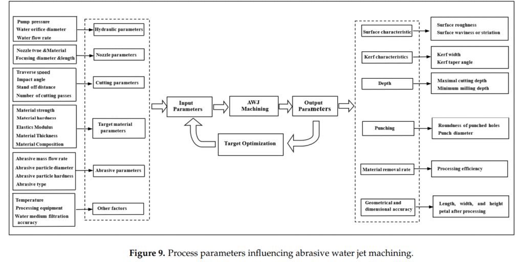
| Pressure Level | Expressed in MPa, it represents the waterjet pressure that a waterjet cutting machine can generate. The higher the pressure, the stronger the cutting ability. The pressure range used in water cutting is 220MPa – 620MPa. Different pressures are selected according to the material characteristics, and the most widely used pressure is 380MPa. |
| Flow Rate | The volume of water ejected per unit time (L/min), which is from 3.7L-12L/min and jointly affects the cutting efficiency with the pressure. |
| Power | The electrical power (kW) consumed during the operation of the waterjet, reflecting the power and cutting ability of the waterjet. The power range is usually from 18KW-75KW, more power needs more energy and cost, 37KW is the balance and used widely. |
| Repeat Positioning Accuracy | Measures the accuracy that a waterjet can achieve in multiple positioning operations, reflecting the stability and reliability of the waterjet. Cutting Accuracy for most water jet table is 0.1mm ,but it could be optimized by some ways like adding angle compensation, impoveing CAD drawing and so on. |
Materials and Processing
| Cutting Materials | Materials that can be cut by a waterjet cutting machine, including metals (such as stainless steel, carbon steel), stone, glass, ceramics, plastics, etc. |
| Cutting Thickness | The maximum thickness of materials that a waterjet can cut. Different models of waterjets have different cutting thickness ranges. For example, if you cut iron, classical APW-A15-B with 37KW could cut less 100mm, while APW-V6P with 75KW could cut less 400mm. |
| Cutting Speed | The moving speed of the cutting head is determined by the transmission device of the cutting platform, such as screw – rod guides or rack – and – pinion. It runs usually 10m/min, but this is much higher than the actual cutting speed. The actual cutting speed needs to be determined by considering factors such as the cutting ability of the waterjet, the characteristics of the cutting material, and the cutting quality. If the process, material, or the operator’s technical level changes, the cutting speed also needs to be adjusted. |
| Cutting Precision | The error range between the actual cutting size and the designed size, generally between ±0.1mm – ±0.5mm. |
| Kerf Width | In abrasive waterjet cutting, the kerf width is directly affected by the diameter of the mixing tube (about 110% of the mixing tube diameter). |
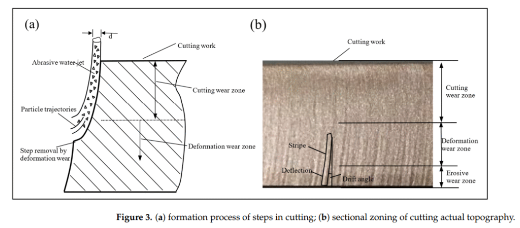
| Cut Quality | Evaluation indicators include cut perpendicularity, roughness, and dross situation. A high – quality waterjet cut should be perpendicular, smooth, and have no obvious dross. |
Cutting Techniques and Skills
| Perforation | Drilling a hole in the material before cutting to allow the waterjet to smoothly enter the material for cutting. The quality of perforation affects subsequent cutting precision. |
| Cutting Path Planning | Optimize the movement path of the cutting head according to the shape of the part to improve efficiency, reduce material waste, and cutting time. |
| Bevel Cutting | Adjust the angle of the cutting head to achieve bevel cutting of the material, meeting specific angular processing requirements. |
| Compensation Cutting | Due to the existence of the kerf width in waterjet cutting, the cutting path is corrected to ensure that the part size meets the design requirements. |
Auxiliary Systems and Devices
| Cooling System | Reduces the heat generated during the operation of the waterjet, prevents components from overheating, and ensures the performance and lifespan of the waterjet. |
| Filtration System | Purifies the cutting water, removes impurities and particles, and avoids wear of the waterjet and blockage of the nozzle. |
| Abrasive – Water Separation Device | Separates the wastewater and waste residue generated during cutting to facilitate wastewater purification and meet environmental protection requirements. |
| Automatic Loading and Unloading System | Realizes automatic loading of materials and automatic unloading of cut parts, improving production efficiency and reducing labor intensity. |
Cutting Quality Evaluation
| Perpendicularity Error | The deviation angle between the waterjet cut and the normal direction of the material surface. The smaller the error, the higher the cutting quality. |
| Flatness | The degree of flatness of the material surface after cutting, reflecting the stability of the waterjet cutting process and the uniformity of the waterjet cutting force. For the same material, the faster the cutting speed, the lower the flatness; at the same speed, the harder the material, the lower the flatness. |
| Edge Chipping | The phenomenon of material chipping at the cutting edge, usually caused by improper waterjet cutting parameters or material characteristics. |
| Heat – Affected Zone | The area on the material surface where the local structure and properties change due to heat during the cutting process. Its size is one of the quality assessment factors. |
Water Jet Abrasive - related
| Abrasive Grain Size | Represents the size of abrasive particles by mesh number. The larger the mesh number, the finer the particles. The commonly used mesh sizes in abrasive waterjet processing are 50 – 220 mesh, and the most common ones are 80 mesh and 120 mesh. |
| Abrasive Flow Rate | The amount of abrasives added to the waterjet per unit time, which directly affects the cutting effect and stability. |
| Abrasive Mixing Ratio | The mass or volume ratio of abrasives to water. An appropriate ratio can enable the waterjet and abrasives to achieve the best synergistic cutting performance. |
Water jet Maintenance and Care
| Sealing Parts | Components (such as sealing rings and gaskets) that prevent the leakage of high – pressure water and abrasives. They need to be regularly inspected and replaced to avoid leakage. |
| Pipeline Cleaning | Regularly clean the water supply and abrasive delivery pipelines to remove impurities, scale, or abrasive residues and ensure the fluid delivery effect. |
| Pump Head Maintenance | Inspect the wear of the pump head of the high – pressure pump and timely replace components such as pistons and sealing rings to ensure stable pump pressure. |
| Electrical System Inspection | Inspect and maintain electrical components such as control cabinets, motors, and sensors to prevent failures and safety accidents. |
Automation and Intelligence - related
| CAD/CAM Integration | Combines CAD design and CAM manufacturing technologies. Through software, cutting paths and parameters are generated to achieve automated programming. |
| Control System | The control system in the motion system converts part programs, speeds, and jet on/off commands into signals that the electrical system can understand. Usually, a CNC control system, a PC – based control system, or a combination of both is used. Engineers design cutting graphics in CAD software, add cutting start/end points, travel directions, cutter compensation, and speeds through CAM software. After the file is sent to the control system, the operator positions the cutting head and starts the cutting. The control system converts the file into electrical current to drive the motors of the machine tool to move and automatically controls the start and stop of water and abrasives. It has the functions of automatically identifying graphics, optimizing paths, and generating parameters, improving programming efficiency and cutting quality. |
| Online Monitoring and Feedback Control | Real – time monitors cutting parameters (such as pressure, flow rate, etc.) through sensors, and the control system automatically adjusts to ensure stability and quality consistency. |
| Robot Integration | Combines the waterjet cutting head with an industrial robot to use the flexibility of the robot to achieve high – precision automated cutting of complex parts. |
Water Jet Technology in Cutting---3 Key Progresses
Water jet technology is an unconventional special process technology; its jet stream has high energy, and its machining process is characterized by no thermal deformation, no pollution, high applicability, and high flexibility. It has been widely used for processing different types of materials in different fields. This review elaborates on the basic principles and characteristics of abrasive water jet processing, the mechanism of erosion, the simulation of the processing, the influence of process parameters in machining removal, and the optimization of improvements, as well as introduces the current application status, new technology, and future development direction of abrasive water jet technology. This review can provide an important information reference for researchers studying the machining processing of abrasive water jet technology.


