The following are the preparation work for equipment installation and the service process provided by our after-sales engineers. The following are the preparation work for equipment installation and the service process provided by our after-sales engineers.
This article is only for reference – for personalized assistance. Contact APW WATER JET SALES. It is every machinery provider’s obligation to help customers maximize profits.
watch water jet cutting videos / download catalogs / check technology data / download APW Waterjet after-sale service process

I. Preparation Work
To ensure the smooth installation of your equipment, the service and operation environment briefing is based on the necessary requirements for equipment installation and operation. Please verify according to the requirements provided by the sales staff (Preparation Items Checklist). After confirmation, please fax back the APW Water jet After-sales Service Form, and we will arrange after-sales personnel to arrive on-site for installation., and we will arrange after-sales personnel to arrive on-site for installation.
II. After-sales Service Process
The on-site after-sales service typically lasts seven days. For specific work arrangements, please refer to the After-sales Service Process table below, which includes equipment installation, debugging, and training.
Preparation Items Checklist
| Category | Specific Requirements |
| Power Supply & Cable | 1. Industrial power supply: 380V 2. Three-phase five-wire system, 3×16 mm²+2 cable (length based on the distance from equipment placement to power source) 3. 100A air switch (without leakage protection) |
| Hydraulic Oil | 1. 46# anti-wear hydraulic oil, 120L 2. Auxiliary oil pumping equipment |
| Water Supply | Air Source |
| Cooling Water | 1. Plastic water tank of 3 tons or more 2. Circulating water pump for cooling hydraulic oil (circulation can be omitted if direct discharge of cooling water is acceptable) |
| Air Source | 1. No less than 2 air supply ports (or Y/T-type air pipe tees for PU8*5 air pipes) 2. Air compressor with compressed air pressure of 6-8KG/cm² and supply > 0.6m³/min |
| Mechanical Tools | 1. One open-end wrench each of 8mm×10mm, 12mm×14mm, 17mm×19mm, 22mm×24mm, 30mm×32mm (5 wrenches total) 2. One adjustable wrench each of 300mm and 375mm (2 wrenches total) 3. 5 rolls of PTFE tape 4. 1 roll of electrical tape 5. Rubber mallet |
| Debugging Tools | 1. Level meter 2. Height gauge 3. Multimeter (can be shared with electricians) 4. Foundation pad irons 5. One impact drill with Φ22mm impact bit |
| Common Electrical Tools | 1. Multimeter 2. Pliers 3. One small and one large flathead/Phillips screwdriver (4 screwdrivers total) |
| Operation Personnel | 1.Trainees: No less than 2 people one free training session provided; basic computer knowledge and fitter skills required 2. Installation personnel: 3 or more people |
| Equipment Installation | 1. Sufficient space around the equipment during installation 2. Placement according to the foundation drawing provided by the company 3. Overhead crane and forklift required 4. Foundation cement thickness ≥ 10CM |
| Water jet Abrasive | 1. Garnet sand (recommended ≥1 ton) |
| Time Arrangement | 1. Installation and debugging: 3-5 days (depending on equipment and site conditions) 2. Training: 2 days The customer should prepare all accessories and tools in advance, and after the person in charge signs and confirms, fax back to arrange engineers according to the requested time. |
After-sales Service Process
| Timeline | Work Content | Tools | Materials |
| Preparations | 1. Customer provides site, equipment factory, and installation preparation photos 2. Engineers determine equipment type and establish installation standards 3. Preparation of service and operation environment 4. For overseas customers: Customer service confirms installation time based on time zones 5. Visa and travel arrangements 6. Travel to site, airport pickup, and arrival at customer location | ||
| Day 1 | 1. Inventory random accessories 2. Confirm completion of preparation work 3. Determine equipment placement 4. Place cutting water tank 5. Install cutting water tank feet 6. Place high-pressure pump 7. Assemble cutting platform Y-axis frame 8. Install cutting platform feet 9. Assemble cutting platform X-axis and Y-axis | 12MM hex wrench, standard hardware tools | |
| Day 2 | 1. Install cutting head 2. Install mini sand tank 3. Install cutting head high-pressure pipe 4. Install two air sources and filter-regulator-lubricator units 5. Install sand supply system 6. Connect equipment air source 7. Connect high-pressure pump and cutting platform high-pressure pipe1. Install cutting head 2. Install mini sand tank 3. Install cutting head high-pressure pipe 4. Install two air sources and filter-regulator-lubricator units 5. Install sand supply system 6. Connect equipment air source 7. Connect high-pressure pump and cutting platform high-pressure pipe1. 安装切割头 2. 安装小型砂箱 3. 安装切割头高压管 4. 安装两个气源及过滤减压阀油雾器组件 5. 安装供砂系统 6. 连接设备气源 7. 连接高压泵与切割平台高压管 | Laser level, height gauge (right scale), standard hardware tools | Hydraulic oil, water pipes |
| Day 3 | 1. Install cutting head 2. Install mini sand tank 3. Install cutting head high-pressure pipe 4. Install two air sources and filter-regulator-lubricator units 5. Install sand supply system 6. Connect equipment air source 7. Connect high-pressure pump and cutting platform high-pressure pipe1. Install cutting head 2. Install mini sand tank 3. Install cutting head high-pressure pipe 4. Install two air sources and filter-regulator-lubricator units 5. Install sand supply system 6. Connect equipment air source 7. Connect high-pressure pump and cutting platform high-pressure pipe1. 安装切割头 2. 安装小型砂箱 3. 安装切割头高压管 4. 安装两个气源及过滤减压阀油雾器组件 5. 安装供砂系统 6. 连接设备气源 7. 连接高压泵与切割平台高压管 | Standard hardware tools | |
| Day 4 | 1. Install cutting water and high-pressure pump cooling water 2. Connect high-pressure pump and CNC to power supply 3. Install water softening system | Scissors, standard hardware tools | Cables, water pipes, pipe connectors |
| Day 5 | 1. Debugging of cutting platform limit positions and zero points 2. Debugging of cutting platform effective stroke 3. Debugging of lubrication system 4. Debugging of X/Y-axis perpendicularity 5. High-pressure pump debugging 6. Cutting system debugging 7. Sample test cutting and equipment running-in 8. Cutting and inspecting samples according to national standards 9. Checking cutting document preparation and simulation | Dial indicator, magnetic base, cast iron right angle plate, multimeter, common hardware tools | |
| Day 6 | 1. Cutting document preparation training: a) Creating compliant DXF files with AutoCAD b) Using NC Studio (5-axis) 2. Basic software operation training: a) CNC system power on/off b) Manual function menu operation c) Automatic function menu operation d) Common parameter settings 3. Practical training: a) Pre-startup preparations b) Abrasive usage (filtration, storage, and sand feed adjustment) c) Air pipe installation and pressure adjustment d) Sand delivery pipe installation e) Manual cutting methods f) Automatic cutting methods | ||
| Day 7 | 1. Practical assessment (trainees draw and cut independently) 2. Practical review and practice: a) Cutting document practice b) Hands-on practice 3. Daily maintenance training 4. Common fault solution training: a) Common cutting platform faults b) Common CNC faults c) Common high-pressure pump faults 5. Equipment acceptance: a) Acceptance after installation and training b) Signing acceptance documents c) Taking photos of the entire equipment and nameplate (for record) d) Collecting customer feedback on equipment issues and improvement suggestions | ||
| End of Service | 1. Departure (airport drop-off) 2. After-sales follow-up by customer service |
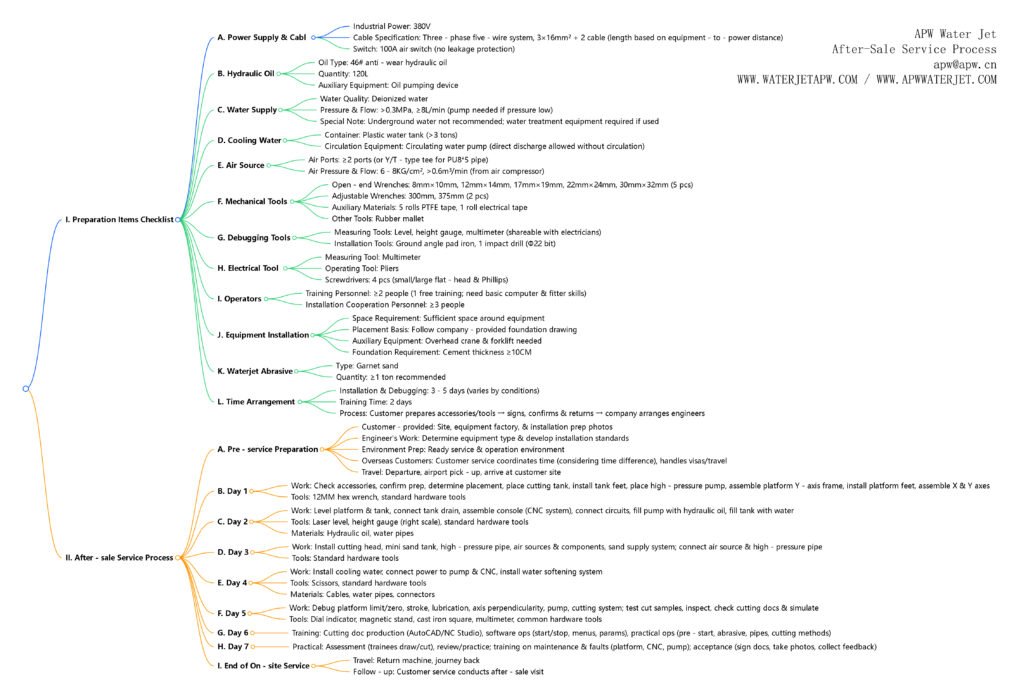
X-mind for after-sale service process


